Aquifer Heterogeneity and Anisotropy
Contents
4. Aquifer Heterogeneity and Anisotropy#
(The contents presented in this section were re-developed principally by Prof. B. R. Chahar and Dr. P. K. Yadav. The original contents are from Prof. Rudolf Liedl)
4.1. Motivation#
The last lecture introduces aquifer properties such hydraulic conductivity, storativity, porosity. The key assumption in that lecture was that the aquifer is an 1D unit, e.g., the Darcy column, and that its properties do not vary in space. In contrast to these, an aquifer is more accurately represented by a 3D system and its properties vary both in space and directions. In fact variations of hydraulic conductivity (\(K\)), a most critical aquifer quantity, are dominant in most cases. Variations of \(K\) can be observed at very small spatial scales and directions. Thus, aquifer properties that depends on \(K\) also varies. Consequently, aquifer properties such as \(K\) takes a tensor form- a quantity whose magnitude is space and direction dependent.
In the picture below (Fig. 4.1) the 3-D spatial variability of aquifer properties is illustrated by a 2-D vertical cross-section. The picture of the outcrop show some form of a layered system, with each layer likely possessing individual subsurface properties.
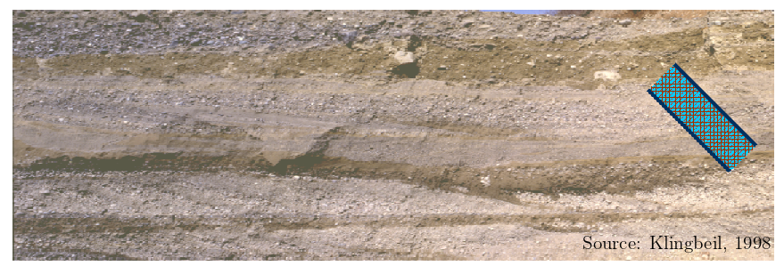
Fig. 4.1 Aquifer Heterogeneity#
4.2. Heterogeneity#
A solid or a porous medium is homogeneous if its property do not vary in space. In contrast, the porous medium is heterogeneous, or also sometime termed inhomogeneous, if at least one of its properties varies in space. In groundwater studies, heterogeneity or homogeneity is generally associated with hydraulic conductivity \((K)\) of the aquifer. In many practical applications, properties such as strativity and porosity are treated as spatially constant or homogeneous. This is usually done for two reasons:
the spatial variability of hydraulic conductivity is much more pronounced than that of storativity and porosity, and
very limited data are available of the spatial variability of storativity and porosity.
Thus, an aquifer is:
homogeneous if \(K (x, y, z) = K\), and
heterogeneous if \(K (x, y, z) \neq K\)
For heterogeneous aquifer it is not required that \(K\) is varying in all directions, i.e., varying of \(K\) can be restricted to one or two spatial coordinates.
Heterogeneity in aquifer can exist in many configurations. But they are broadly categorized to the following three classes:
layered heterogeneity: common in sedimentary systems and unconsolidated deposits.
discontinuous heterogeneity: due to presence of faults, e.g., at the contact between overburden-bedrock.
trending heterogeneity: Common in the aquifers with active sedimentation processes
Aquifer properties such as storativity and porosity are affected by heterogeneity but they are often considered spatially constant in practical applications. This is because
The spatial variability of hydraulic conductivity is much more pronounced than any other aquifer property, and
Only limited spatial variability data are available for storativity or porosity.
Heterogeneity play a significant role in controlling the flow of groundwater, but its quantification is more relevant to the transport of chemicals in groundwater.
4.2.1. Effective Hydraulic Conductivity#
It is possible to represent the spatial distribution of hydraulic conductivity in a heterogeneous aquifer by an average value such that steady-state groundwater discharge remains the same as in the heterogeneous case. Such obtained average \(K\) value is termed as effective hydraulic conductivity. In other words, it can be mentioned that the effective hydraulic conductivity characterizes a fictitious homogeneous aquifer with the same discharge and the same overall head difference under steady-state conditions as some heterogeneous aquifer to be investigated.
The quantification of effective hydraulic conductivity is straight-forward for perfectly layered systems, which can be seen as an idealized representation of natural layering. In more natural systems with complex heterogeneous configurations, cumbersome mathematical derivations are required to obtain effective \(K\).
In the next few sections, effective hydraulic conductivity for ideal layered system is derived.
4.3. Layered Systems#
4.3.1. Case I - Flow Parallel to Layering#
A confined aquifer consisting of \(n\) layers is considered. In the set-up (see Fig. 4.2), the layer boundaries are parallel to each other and groundwater flow is parallel to the layering.
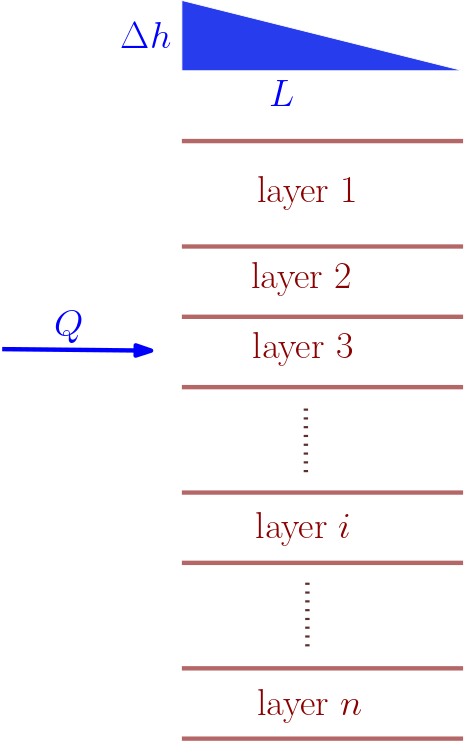
Fig. 4.2 Flow parallel to layering#
The analysis is required to consider the aquifer as a single entire aquifer unit and a set of layered aquifer unit. Data of both units are to be considered.
With these informations available, using volumetric budget and Darcy’s law the effective hydraulic conductivity \(K\) can be quantified from the following steps:
I. Total thickness: \(m = \sum\limits_{i=1}^n m_i\)
II. Volumetric budget: \(Q = \sum\limits_{i=1}^n Q_i\)
III. Head loss in \(i^{th}\) layer: \(\Delta h_i = \Delta h\)
IV. Darcy’s law for \(i^{th}\) layer: \(Q_i = - wm_iK_i\frac{\Delta h}{L} \)
V. Darcy’s law for the homogeneous aquifer to replace the layered system: \(Q = -wmK\frac{\Delta h}{L}\)
Note
As flow is parallel to the layering, the head loss in individual layer equals the total head loss (step. 3)
Summing the discharge in each layer (step 4) will result to the discharge of the homogeneous aquifer (step 5), i.e., we can equate step 4 and step 5 as:
Constant quantities from the right-hand side can be taken out of summation and equated with the left side. This leads to:
providing
As a result, the effective hydraulic conductivity of a layered system when the flow is parallel to the layering equals
In the above equation, effective hydraulic conductivity \(K\) is obtained as the weighted arithmetic average of layer conductivities \(K_i\). Weights correspond to relative thickness \(m_i/m\). Thus, the largest term in the sum contributes most to the arithmetic average. Thus, the effective hydraulic conductivity \(K\) can be approximated from
4.3.2. Example problem#
Flow parallel to layering
Calculate the effective hydraulic conductivity of the layer system consisting of 3 layers if the flow is parallel to the stratification.
 Provided are:

thickness of layer 1 = 3 m
thickness of layer 2 = 2.5 m
thickness of layer 3 = 1.75 m

conductivity of layer 1 = 3.5e-03 m/s
conductivity of layer 2 = 2.0e-02 m/s
conductivity of layer 3 5.0e-04 m/s
import numpy as np

#Thickness of i-th layer [m]
m1 = 3
m2 = 2.5
m3 = 1.75

#conductivity of i-th layer [m/s]
K1 = 3.5e-3
K2 = 2e-2
K3 = 5e-4

#intermediate calculation
m = m1+m2+m3

#solution
K = (m1*K1+m2*K2+m3*K3)/m

print("\n\033[1mSolution:\033[0m\nThe resulting hydraulic conductivity of the layer system is \033[1m{:02.1e} m/s\033[0m.".format(K))
Solution:
The resulting hydraulic conductivity of the layer system is 8.5e-03 m/s.
4.3.3. Case 2 - Flow Perpendicular to Layering#
In the second case the the flow perpendicular to the layering is considered. Just as in the parallel flow case, the aquifer in this case also is a confined aquifer with \(n\) layers (see Fig. 4.3).
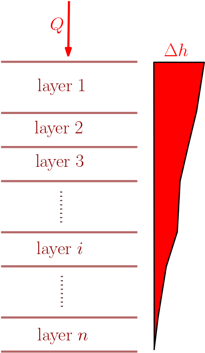
Fig. 4.3 Flow perpendicular to layering#
These data combined with equation of continuity and Darcy’s Law can be used to obtain the effective hydraulic conductivity of the system in which flow is perpendicular to the layers. The following steps are required:
I. Total thickness: \(m = \sum\limits_{i=1}^n m_i \)
II. Equation of continuity: \(Q_i = Q\)
II. Cross-sectional area for layer: \(A_i = A \)
IV. Decomposition of head loss: \(\Delta h = \sum\limits_{i=1}^n \Delta h_i \)
V. Darcy’s law for layer \(i\):
VI. Similarly the Darcy’s law for the homogeneous aquifer to replace the layered system:
VII. The head loss from step 4 can be equated with the sum of head loss of each layered unit (from step 5), i.e.,
The constants \(Q\) and \(A\) can be taken out of the summation, this leads to
As a result, the effective hydraulic conductivity of a layered system for a flow perpendicular to the layering equals
In the above equation, effective hydraulic conductivity \(K\) is obtained as the weighted harmonic average of layer conductivities \(K_i\). Weights correspond to relative thicknesses \(m_i/m\). Thus, the largest term in the sum contributes most to the harmonic average and therefore, the effective hydraulic conductivity can be approximated from
4.3.4. Example problem#
Flow perpendicular to layering
Calculate the effective hydraulic conductivity of the layer system consisting of 3 layers if the flow is perpendicular to the layering.
 Provided are:
thickness of layer 1 = 3 m
thickness of layer 2 = 2.5 m
thickness of layer 3 = 1.75 m

conductivity of layer 1 = 3.5e-03 m/s
conductivity of layer 2 = 2.0e-02 m/s
conductivity of layer 3 5.0e-04 m/s
#Thickness of i-th layer [m]
m1 = 3
m2 = 2.5
m3 = 1.75

#conductivity of i-th layer [m/s]
K1 = 3.5e-3
K2 = 2e-2
K3 = 5e-4

#intermediate calculation
m = m1+m2+m3

#solution
K = m/(m1/K1+m2/K2+m3/K3)


print("\n\033[1mSolution:\033[0m\nThe resulting hydraulic conductivity of the layer system is \033[1m{:02.1e} m/s\033[0m.".format(K))
Solution:
The resulting hydraulic conductivity of the layer system is 1.6e-03 m/s.
4.3.5. Summary: Effective Conductivity of Layered Aquifers#
For flow parallel to layering:
Effective hydraulic conductivity equals the weighted arithmetic mean of layer conductivities.Flow perpendicular to layering:
Effective hydraulic conductivity equals the weighted harmonic mean of layer conductivities.Weights in both cases are given by relative layer thicknesses \(m_i/m\)
It can be mathematically shown that the harmonic mean of a set of positive numbers cannot exceed the arithmetic mean of the same set. Both means are identical only if all numbers in the set are identical. Apart from this very special case, we have
Note
harmonic mean < arithmetic mean.
This implies that the flow direction perpendicular to the layering is associated with a smaller effective hydraulic conductivity than the flow direction parallel to the layering.
4.4. Hydraulic Resistance#
The Hydraulic Resistance \((R)\) provide an alternative approach to express conductivity. It is defined as a reciprocal to hydraulic conductivity \((K)\), i.e.,
This implies that large \(K\) corresponds to small \(R\) and vice-versa. Considerations about effective hydraulic conductivities of layered aquifers can be transferred to hydraulic resistances by recalling that the arithmetic mean of positive numbers coincides with the harmonic mean of reciprocal numbers and vice versa. This can be used in the following manner:
For flow parallel to layering:
As Effective hydraulic conductivity equals the weighted arithmetic mean of layer conductivities, the reciprocal of this, i.e., the effective hydraulic resistance, will equal the weighted harmonic mean of layer resistances.
Furthermore, if all layer thicknesses are identical \((m_i =\) const.) and flow is parallel to layering, the largest discharge passes through the layer with highest hydraulic conductivity (smallest hydraulic resistance). In this case, the discharge through each layer is proportional to layer conductivity or inversely proportional to layer resistance.
For flow perpendicular to layering:
In this case the effective hydraulic conductivity equals the weighted harmonic mean of layer conductivities. This leads to Effective hydraulic resistance equaling the weighted arithmetic mean of layer resistances.
Similar to the flow parallel to the layering, if all layer thicknesses are identical (\(m_i =\) const.) and flow is perpendicular to layering, the largest hydraulic gradient is across the layer with lowest hydraulic conductivity (highest hydraulic resistance). In this case, the head gradient across each layer is proportional to layer resistance or inversely proportional to layer conductivity.
4.4.1. Example problem#
Hydraulic Resistance
Find the hydraulic resistance with the given hydraulic counductivity
 Provided are:

Hydraulic conductivity = 5.0e-04 m/s
K = 5e-4 # m/s, hydraulic conductivity
#solution
R = 1/K
print("\n\033[1mSolution:\033[0m\n\nThe resulting hydraulic resistance is \033[1m{:02.1e} s/m\033[0m.".format(R))
Solution:

The resulting hydraulic resistance is 2.0e+03 s/m.
4.5. Aquifer Anisotropy#
A solid or a porous medium is isotropic if its (all) properties are independent of direction. Conversely, a solid or a porous medium is anisotropic if at least one of its property is dependent on direction. Thus, isotropic (or anisotropic) property of porous media refines the concept of homogeneity (or heterogeneity). The key difference being that anisotropy of aquifer is associated only with hydraulic conductivity as other aquifer properties like storativity or porosity cannot depend on direction. Groundwater flow (and more so solute transport) is affected by anisotropy. However, in unconsolidated aquifers the impact of heterogeneity is usually more important.
Figure below (Fig. 4.4) explains the concept of isotropy more clearly. The direction dependency of \(K\) is represented by the arrows diagram.
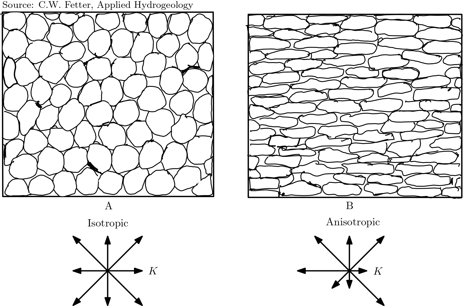
Fig. 4.4 Isotropy and Anisotropy in aquifers#
4.5.1. Anisotropy and scale effects#
The effective hydraulic conductivity of layered aquifers was shown earlier to depend on the orientation of the flow direction relative to layering, i.e., parallel versus perpendicular. On a larger scale, it may not be possible to identify or resolve heterogeneities associated with example thin layers, small lenses, shape and orientation of grains (see figure above). Nevertheless, \(K\) is found to be direction-dependent when groundwater flow is quantified at the larger scale. In these case, small-scale heterogeneity (e.g., due to layering) expresses itself as anisotropy of hydraulic conductivity at the larger scale.
4.5.2. Indices and functional arguments to describe anisotropy#
One could consider heterogeneity as a property of entirety. While function arguments point towards heterogeneity, indices are used to express that hydraulic conductivity depends on direction. Considering a 3-D Cartesian coordinate system, the directional dependent hydraulic conductivity can be represented by \(K_x\), \(K_y\) and \(K_z\) in parallel with the \(x-\), \(y-\) and \(z-\)axis, respectively. Within these, one could distinguish between horizontal conductivities (\(K_x\) and \(K_y\)) with the vertical conductivity \(K_z\). More often, anisotropy is observed only between horizontal and vertical directions (i.e., along \(x\) or \(y\) and \(z\) directions), while isotropy is observed along horizontal directions (\(x\) and \(y\) direction). Thus, symbols \(K_h\) representing \(K_x = K_y\) and \(K_v\) representing \(K_z\) can be used to denote horizontal and vertical hydraulic conductivity, respectively.
4.5.3. Concept of the hydraulic conductivity ellipse#
Let us consider an aquifer with horizontal conductivity \(K_h\) and vertical hydraulic conductivity \(K_v\). Let us assume that the flow in the aquifer is in some arbitrary direction characterized by the angle \(\theta\) between the flow direction and horizontal plane (see Fig. 4.5).
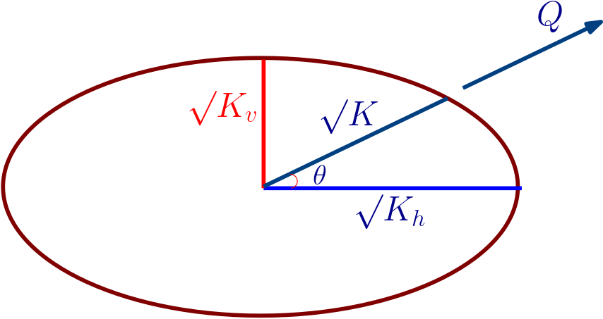
Fig. 4.5 hydraulic conductivity ellipse#
In this case, it can be shown that the effective hydraulic conductivity \(K\) is
If the angle \(\theta\) is varied, the above equation defines an ellipse (also called “hydraulic conductivity ellipse”) with semi-axes equal to \(\surd{K_h}\) and \(\surd{K_v}\), respectively. The square root of \(K\) can be visualised by the length of a line segment parallel to the direction of flow. This line segment extends from the centre to the perimeter of the ellipse.
4.5.4. Example problem#
Hydraulic Resistance
Find resulting hydraulic conductivity from provided horizontal and vertical conductivities.
Provided are:

horizontal hydraulic conductivity = 1.0e-03 m/s
vertical hydraulic conductivity = 1.0e-04 m/s
angle = 50°
#solution
K = 1 /((np.cos(theta)**2/Kh)+(np.sin(theta)**2/Kv))


print("\033[1mSolution:\033[0m\n\nThe resulting hydraulic conductivity is \033[1m{:02.1e} m/s\033[0m.".format(K))
Solution:

The resulting hydraulic conductivity is 6.2e-04 m/s.
4.6. Combining Heterogeneity and Anisotropy#
The distinction between_Homogeneous, Heterogeneous, isotropic and anisotropic aquifer or any combination of them can be more clearly understood from the figure (for vertical \(x-z\) plane).
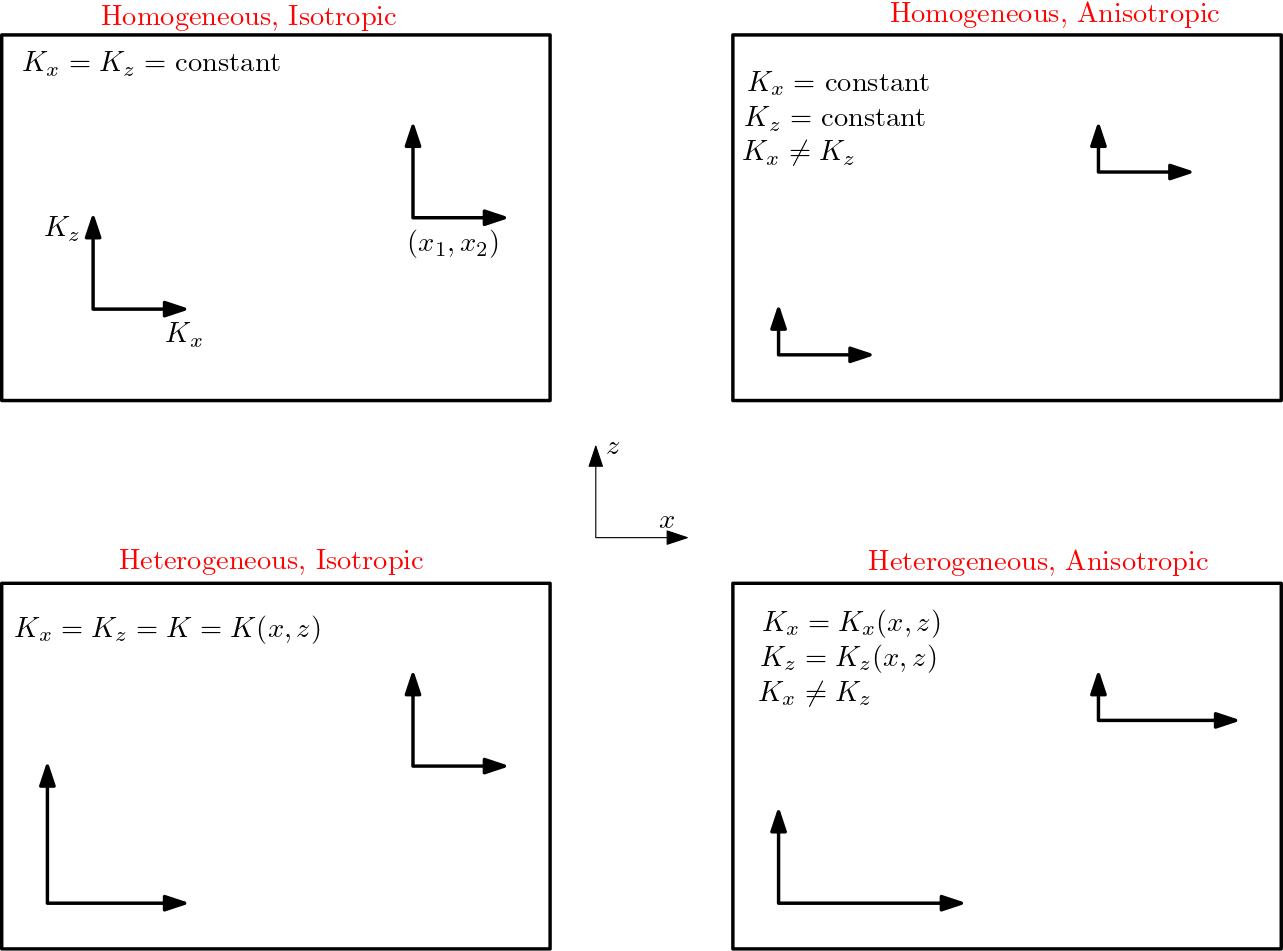
Fig. 4.6 Heterogeneity and Anisotropy in aquifer#


