Wells
Contents
7. Wells#
(The contents are based on the class lecture materials of Prof. R. Liedl. Modifications mostly to fit this specific format were done by Prof. Liedl and Dr. P. K. Yadav.)
7.1. Motivation#
In the last lecture (Quantifying 3D Groundwater Flow we derived system equations for different groundwater flow problems. We realized of the difficulties associated with solving flow problems specially at higher dimensions (2D/3D). Numerical methods are mostly used for solving groundwater problems but direct (analytical) solutions are also possible for some problems.
Wells are the most common and also most extensively used method of utilizing (or affecting) groundwater. Thus, wells represent a very common groundwater problem. We can now use our understanding of aquifer properties and groundwater system equations to analyze effect of wells on the natural groundwater flow. We will however restrict our extent, in this lecture, to problems that can be directly solved. After learning numerical methods (in last part of this course), we will apply it to evaluate more complex groundwater problems also associated with wells.
We begin this lecture recalling groundwater storage property transmissivity. Introducing wells we then derive few relations that can help us understand the effect of wells in groundwater flow. To conclude, we will use the wells to characterize aquifers, i.e., using so called pumping test.
7.2. Transmissivity#
When discussing storage properties in Groundwater as a reservoir, we saw that aquifers or single layers may frequently be treated as two-dimensional systems. This is justified because the lateral extension of aquifers is usually much larger than the vertical extension. Thus, vertical variations of storage properties can be replaced by some average value without adversely affecting the quantification of groundwater storage.
Similar things can be done with regard to conductivity properties and this brings us to the geohydraulic parameter of transmissivity (\(T\), L\(^2\)T\(^{-1}\)). The idea is to neglect vertical variations of hydraulic conductivity and to use vertically averaged values instead. This procedure does not eliminate horizontal variability, so transmissivity may still depend on horizontal coordinates \((x, y)\).
The vertically averaged \(K\) value is then multiplied by the water-saturated thickness to obtain transmissivity. The concept of water-saturated thickness (or water-saturated depth) requires to distinguish whether confined or unconfined flow conditions prevail.
In general, water-saturated thickness is the distance from the aquifer bottom to a level up to which all pores are filled with water. For confined aquifers, this level is equal to aquifer top and water-saturated thickness is tantamount to aquifer thickness. For unconfined aquifers, however, water-saturated thickness corresponds to the distance between aquifer bottom and groundwater level. We will see some illustrations below when we try to quantify transmissivity.
Let us have a closer look at the confined case first. The black cuboid in Fig. 1.1 illustrates that water-saturated thickness extends from aquifer bottom to aquifer top. So, it is equal to aquifer thickness \(m\). Transmissivity is calculated by \(T_x = K_x \cdot m\) and \(T_y = K_y \cdot m\). Here we allow for horizontal aquifer anisotropy with different hydraulic conductivities in \(x-\) and \(y-\) direction \((K_x\neq K_y)\). For horizontally isotropic aquifers \((K_x = K_y = K)\), transmissivity is given by \(T = K \cdot m\).
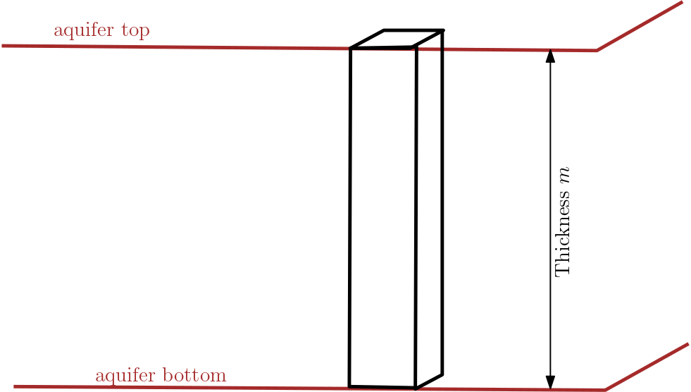
Fig. 7.1 The transmissivity cuboid in confined aquifer.#
Things are a bit more complicated for unconfined aquifers. Fig. 7.2 illustrates that water-saturated thickness extends from the aquifer bottom to the groundwater table. It is important to note that transmissivity of unconfined aquifers depends on the vertical position of the groundwater table. For instance, if the groundwater table is lowered during to a draught period, transmissivity is decreasing. This is fundamentally different from the confined case where the water-saturated thickness is given by aquifer geometry only and is not affected by hydraulic head changes.
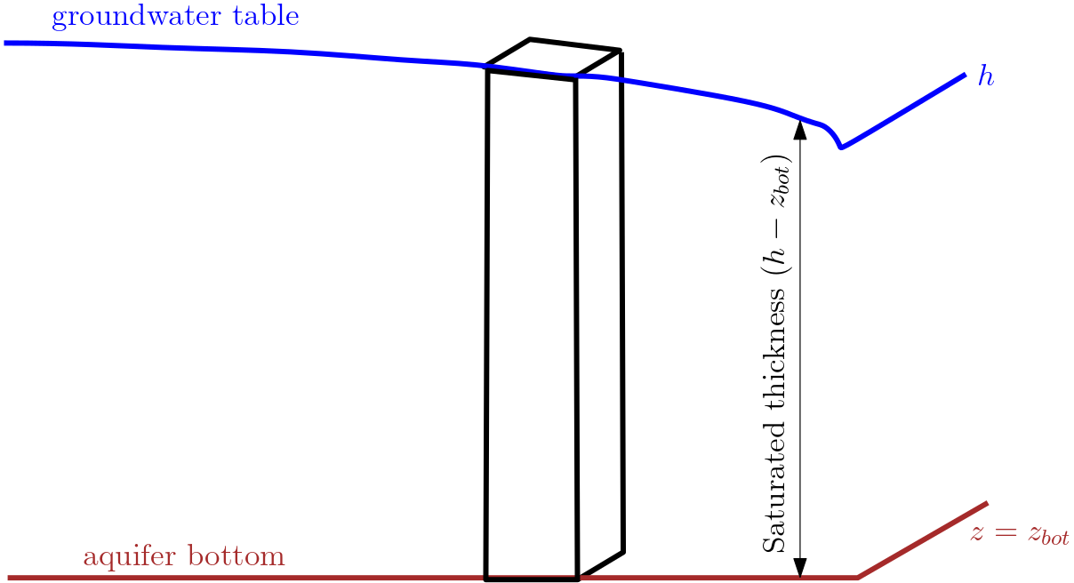
Fig. 7.2 The transmissivity cuboid in unconfined aquifer.#
Computing transmissivity of unconfined aquifers requires to determine the difference of hydraulic head h and the elevation of aquifer bottom \(z_{bot}\). Based on this, transmissivity is given by \(T_x = K_x\cdot(h - z_{bot})\) and \(T_y = K_y\cdot(h - z_{bot})\). As above, we are allowing for horizontal aquifer anisotropy. For an isotropic unconfined aquifer we get \(T = K\cdot(h - z_{bot})\).
Two more remarks appear to be appropriate: First, transmissivity may be computed by the given equations even if the aquifer bottom is not horizontal. This case is not covered by the Fig. 7.2. Second, textbooks frequently present the equation \(T = K\cdot h\) for transmissivity of unconfined aquifers. It is to be noted that this equation only holds if two conditions are fulfilled:
Required conditions when \(T = K\cdot h\) is valid
The aquifer bottom must be horizontal, and
hydraulic head values are expressed with respect to the elevation of aquifer bottom (= reference datum).
Finally, we can try to compute transmissivity for isotropic aquifers and check how the result depends on several quantities like aquifer bottom, aquifer top, and hydraulic head.
7.2.1. Example problem#
Transmissivity
Find if the aquifer is confined or unconfined, and then calculate transmissivity of the aquifer.
K_a = 8.5e-05 # m/s, Hydraulic conductivity
Z_bot = 120 # m, aquifer bottom
Z_top = 150 # m, aquifer top
h_a   =  139 # m, hydraulic head in aquifer

# interim calculation
A_t = Z_top-Z_bot # m, Aquifer thickness
A_wt = h_a - Z_bot # m, water_table level
S_t = min(A_t, A_wt) # m, saturated thickness

# result
if h_a<Z_top:
    print("It is Unconfined Aquifer \n")
else:
    print("It is Confined Aquifer \n")

T_a = K_a*S_t # m^2/s, transmissivity

print("The required transmissivity is {0:1.2e}".format(T_a), "m\u00b2/s")
It is Unconfined Aquifer

The required transmissivity is 1.62e-03 m²/s
7.3. Wells - Overview#
7.3.1. What is a Well?#
A well is a shaft or a hole that has been sunk, dug or drilled into the earth to extract water (source: Glossary of Hydrology).
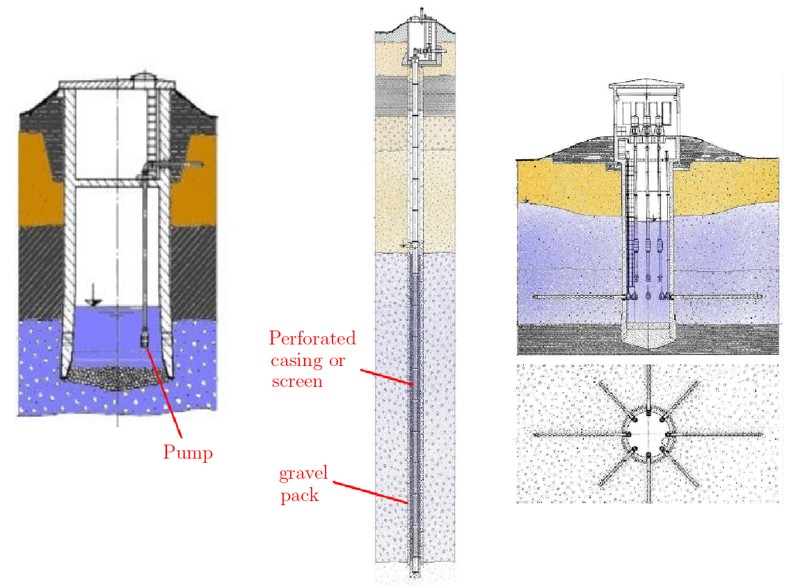
Fig. 7.3 Well and its components.#
7.3.2. Using wells#
Wells are very extensively used around the globe. The contents below only highlights few of the use of wells.
Water supply: e.g., for households, agriculture, industry
Lowering the groundwater level: e.g., for excavations, open-pit mining
Remediation of aquifer contamination: e.g., applying pump and treat method.
Aquifer characterisation: e.g., using pumping test (this lecture)
Apart from aquifer characterisation, wells are usually operated at steady-state i.e., at constant pumping rate. The figure below presents different uses of wells. Fig. 7.4 shows the case of lowering the groundwater level at the excavation site. The lowering is very often observed at the works that requires sub-surface construction works, e.g., high-rise building, tunnels. For this wells are placed close to excavation works and water is pumped out at higher discharge rates compare to the groundwater replenishing rate. This leads to decline of water level at the excavation site.
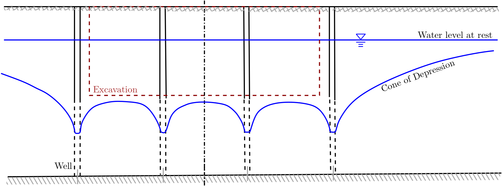
Fig. 7.4 Well at the excavation site#
Fig. 7.5 presents the case of using wells to delineate contamination site from the groundwater. These are part of the development of sanitary landfills sites or industries that pose threat to groundwater quality. Wells are used to lower groundwater table such that seepage of refuse is contained in the limited region.

Fig. 7.5 Well at the refuse site#
7.3.3. Fully versus Partially Penetrating Wells#
Fully penetrating wells: : The fully penetrating wells are those which extends through the whole saturated depth of an aquifer and are constructed in such a manner that water is permitted to the well screen over its length Glossary of Hydrology).
Fig. 7.6 shows a schematic of water flow in a fully penetrating wells.

Fig. 7.6 Flownet in a fully penetrating wells#
Partially penetrating Wells: : The partially penetrating Wells are those in which the length of water entry is less than the thickness of the saturated aquifer which it penetrates (Glossary of Hydrology).
Partially penetrating wells are constructed when aquifer depths are very high; in which case a fully penetrating well may not also be economical. Fig. 7.7 presents a schematic of a flownet that is likely to be observed in the partially penetrating well.
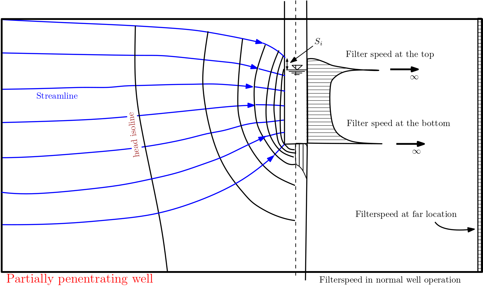
Fig. 7.7 Flownet in a partially penetrating wells#
Comparing the Flownets in Fig. 7.6 and Fig. 7.7, it can be observed that the vertical flow components can be significant in the partially penetrating case. This then lead to a 3D groundwater problem compared to the fully penetrating case, which can be treated as 2D groundwater problem as vertical flow component has limited effect.
This course we will deal only with the fully penetrating steady-state cases.
7.4. Groundwater Flow Near Wells Operated at Steady State#
As stated earlier wells are mostly operated under steady-state condition. Here will attempt to quantify the case. We will first attempt to identify the most relevant problems associated with the steadily pumping wells and then define our approach to solve them. The two most important points that need to be addressed here are:
Which relevant quantities are needed to describe steady-state flow towards a well?
What is the quantitative relationship between the hydraulic parameters under steady-state conditions?
To answer the above questions, we follow the following approach:
Find an appropriate way to apply the law of continuity (conservation of volume) and Darcy‘s law.
We delineate the problem, e.g., study the confined and the unconfined cases separately.
7.4.1. Cone of Depression in a Confined Aquifer#
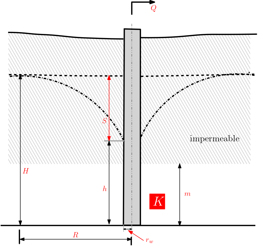
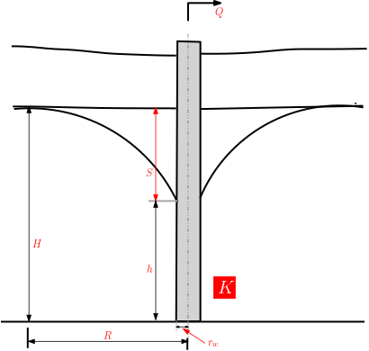
A cone of depression (or drawdown cone) will result when the well pumps groundwater groundwater is pumped from the well. Fig. 7.8 presents the schematic with relevant quantities of a well pumping case in both confined and unconfined aquifers. In both cases the well is fully penetrating. As can be understood from the figure that in the unconfined case the drawdown (\(s\)) magnitude depends on the water table level. This in the case of confined aquifer is dependent on the hydraulic head.
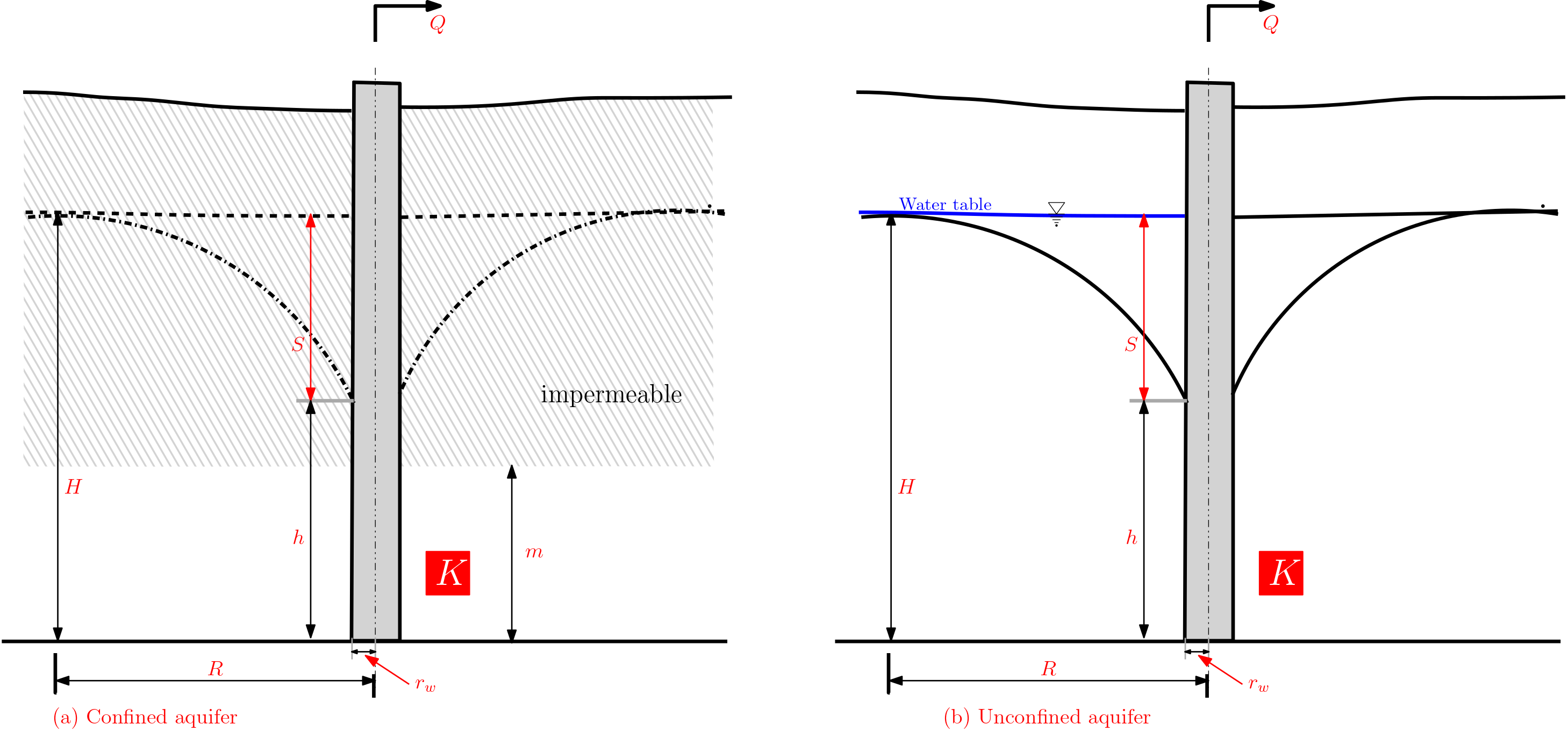
Fig. 7.8 Cone of depression in a (a) confined Aquifer and (b) unconfined aquifer (right)#
Relevant quantities in the figure:
pumping rate \(Q\) [L\(^3\)T\(^{-1}\)]
aquifer thickness \(m\) [L]
hydraulic conductivity \(K\) [LT\(^{-1}\)]
water level at rest \(H\) [L]
water-level in the well \(h\) [L]
Radius of influence \(R\) [L]
well radius \(r_w\) (incl. gravel pack!)[L]
drawdown \(s = H - h\) [L]
The Radius of influence (\(R\)) in the figure is the distance from the well at which the drawdown becomes negligible or unobservable. Thus \(R\) delineates the influence of the well on the normal groundwater flow.
7.4.1.1. Evolution of Cone of Depression with Time#
Transient models have to be used to observe the evolution of cone of depression. These are mostly only possible through use of numerical models (to be discussed in the later end of this course). The animation provides the computer simulation of evolving cone of depression as a function of time. From the figure it is easier to obtain the radius of influence (\(R\)). It is to be noted that \(R\) will be maximum at the steady-state condition.
video1 = pn.pane.Video("images/L08_f9X.mp4", width=400, height=150, loop=False)
spacer = pn.Spacer(width=50)
image = pn.pane.PNG("images/L08_f9Y.png", width=200)
pn.Row(video1, spacer, image)
7.4.2. Law of Continuity#
Next we attempt to quantify the cone of depression. For this, and it is common in any hydraulics study, we begin with the Law of Continuity. Overall law of continuity implies:
Law of Continuity
Discharge \(Q_w = \) constant
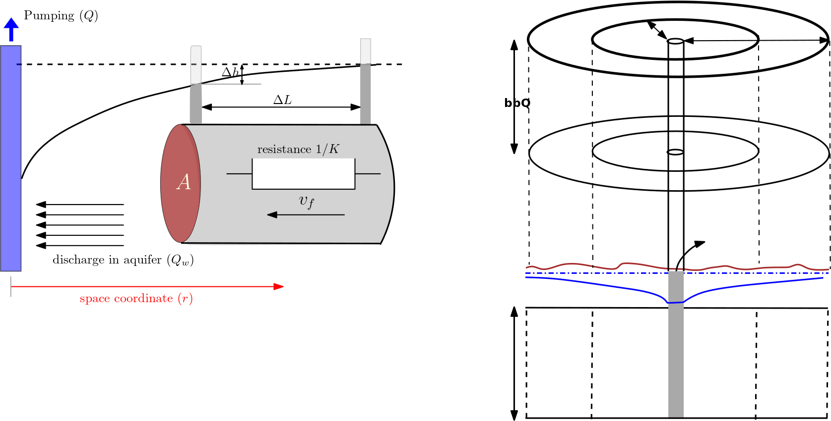
Fig. 7.9 Graphic visualization of Law of quantity.#
This, also seen in Fig. 7.9, implies that the pumping rate \(Q\) corresponds to the discharge \(Q_w\) near the well. Further, under steady-state conditions the law of continuity implies that there is the same discharge at all cross sections which completely surround the well (“mantle of a cylinder”).
7.4.3. Darcy’s Law for Flow Towards a Well in a Confined Aquifer#
The Darcy’s law, as we have known so far, relates the Darcy’s velocity \(v_f\) and the hydraulic gradient \(i\). If the hydraulic gradient was constant in space, the hydraulic gradient would be (also see Fig. 7.9 )
where, \(r\) represents the radial distance from the well axis. In this case the hydraulic gradient \(i\) depends on the distance \(r\) within a cone of depression Fig. 7.9). Qualitatively, it can be understood that \(i\) is decreasing with increasing distance from the well. Since the hydraulic gradient is not constant in space, the ratio \(\frac{\Delta h}{\Delta r}\) has to be replaced by
With this defined, the Darcy’s law should be expressed as function of \(r\) as
And, now introducing the continuity equation we obtain:
with \(A\) is the area of a cross section at distance \(r\) from the well axis. Therefore \(A\) is
\(A\) is now inserted to eq. (C3), This results to
Eq (C5) is a first-order differential equation for hydraulic head \(h(r)\). It can be solved by separation of variable. Doing that eq. (C5) becomes $\( \textrm{d}h(r) = \frac{Q_w}{2\cdot \pi \cdot m \cdot K }\cdot \frac{\textrm{d}r}{r} \tag{C6} \)$
We now integrate eq. (C6). The limit of integration (see figure) along the vertical direction (\(h\)) will be from \(h\) to \(H\), and that along the radial axis will be from \(r_w\) and \(R\), i.e., we get
The integrals in eq. (C7) are direct integrals and can be obtained from the table of integrals. The eq. (C7) with the indefinite integrals is thus
after inserting the limits of integration, we get
Finally, we can solve for the discharge \(Q_w\) and obtain
The negative sign on the right-hand side of eq. (C9) indicates that flow is anti-parallel to the direction of the coordinate axis. Frequently, the pumping rate \(Q\) is used instead of \(Q_w\) and the negative sign is omitted. Thus we get a well known solution called Theim equation after Thiem (1906)1
with decadic logarithm, we get,
7.4.4. Example problem#
Well discharge from confined aquifer
From the provided data, calculate the transmissivity of the aquifer.
 Provided are:

 The given dscharge is: 9 m³/min

 The distance to Well 1 and well 2 are: 8m and 22m

 The head at Well 1 and well 2 are: 9m and 10m
7.4.4.1. Solution#
For confined aquifer \(T = K\cdot m\), the Thiem equation can be modified as:
Q = 9 # m^3/min, Given discharge
r1 = 8 # m, distance from well to point 1
h1 = 9 # m, head at well 1
R2 = 22 # m, distance from well to point 2
H2 = 10 # m, head at well 2


#interim calculation
Q_min = Q * 1440 # m^3/d

#Calculation

T = Q/(2*np.pi*(H2-h1))*np.log(R2/r1) # m^2/d, Transmissivity - inverting Theim equation

print("\n\033[1m Result:\033[0m\n")
print("The transmissivity in the aquifer is {0:0.2f} m\u00b2/d".format(T))
 Result:

The transmissivity in the aquifer is 1.45 m²/d
7.5. Flow Towards a Well in an Unconfined Aquifer#
In the unconfined aquifer, the hydraulic head is function of \(r\). Thus the discharge in the aquifer:
Also in this case, the cross section area \(A\) also is dependent on \(r\), i.e.,
Next, we insert eq (U2) in eq. (U1) and get
Eq. (U3) is a first-order differential equation for hydraulic head \(h(r)\), and it can be solved by separation of variables. Separating the variables of eq. (U3) leads to
Next we integrate eq. (U4) from limits \(r_w\) to \(R\) in the right-hand side, and from \(h\) to \(H\) (left-hand side), i.e.,
The integral in eq. (U5) can be obtained from the standard table of integrals. With that we get
The discharge in aquifer \(Q_w\) can be obtained from eq. (U6) and the expression is
The negative sign on the right-hand side of the eq. (U6) indicates that flow is anti-parallel to the orientation of the coordinate axis. Frequently, the pumping rate \(Q\) is used instead of \(Q_w\) and the negative sign can thus be omitted, and we get
In the decadic logarithm, the discharge from the well is:
7.5.1. Example problem#
Well discharge from unconfined aquifer
From the provided data, calculate discharge of the aquifer.
print("\n\033[1m Provided are:\033[0m\n")

K = 24.50 # m/d, conductivity
r_1 = 0.23 # m, distance from well to point 1
h_1 = 12 # m, head at well 1
R_2 = 275 # m, distance from well to point 2
H_2 = 18 # m, head at well 2

print(" The given conductivity is: {}".format(K), "m/d \n")
print(" The distance to Well 1 and well 2 are: {} m and {} m are \n".format(r_1, R_2))
print(" The head at Well 1 and well 2 are: {} m and {} m".format(h_1, H_2))

#Calculation

Q_1 = (np.pi*K*(H_2**2-h_1**2))/(np.log(R_2/r_1)) # m^2/d, Transmissivity - inverting Theim equation

print("\n\033[1m Result:\033[0m\n")
print("Discharge from the well is {0:0.2f} m\u00b3/d".format(Q_1))
 Provided are:

 The given conductivity is: 24.5 m/d

 The distance to Well 1 and well 2 are: 0.23 m and 275 m are

 The head at Well 1 and well 2 are: 12 m and 18 m

 Result:

Discharge from the well is 1955.06 m³/d
7.5.2. Radius of Influence#
The radius of influence (\(R\)) can also (instead of using numerical simulations) be obtained from empirical equations. The table below provides a list of few equations.
Source |
Equation |
|
|---|---|---|
Lembke (1886, 1887) |
\(R = H (K/2\cdot N)^{1/2}\) |
|
Weber (Schultze, 1924) |
\(R = 2.45 (H\cdot K\cdot t/S)^{1/2}\) |
|
Kusakin (Aravin and Numerov, 1953) |
\(R = 1.9 (H \cdot K \cdot t/s)^{1/2}\) |
|
Siechardt (Certousov, 1962) |
\(R = 3000\cdot s \cdot K^{1/2}\) |
|
Kusakin (Certousov, 1949) |
\(R = 575\cdot s \cdot (H \cdot K)^{1/2} \) |
Siechardt and Kusakin equation are among the preferred equations by practitioners. In both equations, \(K\) has to be expressed in m/s and all other quantities must be expressed in m. R depends on drawdown \(s= H-h\) in both equations. Trial and error or iterative strategies have to be used to determine \(R\) and \(h\).
7.6. Aquifer Characterisation by Pumping Tests#
Pumping tests are used to estimate aquifer properties such as hydraulic conductivity \((K)\), transmissivity \((T)\) or storativity \((S)\). Pumping results in an evolving cone of depression as was discussed earlier (see Fig. 7.8). The decrease in hydraulic head (or increase in drawdown) with time is recorded in one or more observation wells (and sometimes also in the pumping well itself).
A variety of different schemes exist to evaluate pumping test data. The appropriate method has to be selected according to the specific setting (confined or unconfined, layered system, horizontal or inclined aquifer bottom etc.). A well known approach to derive \(T\) and \(S\) from pumping test data was developed by Theis (1935)2
7.6.1. Applicability of the Theis Method#
Pumping test data can be evaluated according to Theis (1935) if the following assumptions are (approximately) justified:
The aquifer is confined, homogeneous and isotropic.
The aquifer thickness is uniform.
The aquifer bottom is horizontal.
The well is fully penetrating.
The well radius is very small as compared to the radius of influence.
The pumping rate is constant within the measurement period.
There is no vertical flow component.
The evolution of the cone of depression is not influenced by other hydraulic factors (surface water, impermeable boundaries etc.).
7.6.2. Drawdown According to Theis (1935)#
Theis (1935) deals with the transient flow (as opposed to steady-state methods discussed above) of water to a pumping well. The time-dependent drawdown \(s\) in an observation well, which is a distance \(r\) apart from the pumping well, is given by
where, \(W(u)\) is the well function, which is given as
in which \(u\) is defined by
where \(S\) [-] is storage coefficient. For application Eq (T1) and eq. (T2), these equation are log-transformed. Eq (T1) then becomes
and upon log-transformation and rearrangement of eq. (T2) results to
These two equations are used to derive \(T\) and \(S\) from drawdown data. This can either be done by applying special computer software or manually by a graphical method, which is discussed next.
7.6.3. Manual Comparison of Data and Type Curve#
Theis (1935) provides a graphical approach to use the Theis equation. The following steps are to be followed for using the graphical approach:
The logarithm of drawdown (\(\log s\)) is plotted against the \(\log(t/r^2)\) in the data sheet
The logarithm of the well function \((\log W(u))\) is plotted against \(\log (1/u)\) in a type curve sheet.
Both sheets are put on top of each other such that the data coincide with some part of the type curve.
The shifts along the vertical and the horizontal axes correspond to the constant terms in the equations
The constant term in the upper equation (\(\log\frac{Q}{4\cdot \pi \cdot T}\)) can then be solved for \(T\).
Finally, the constant term \((\log\frac{S}{4 T})\) in the lower equation can be used to solve for \(S\).
Important
The Type curve is independent from aquifer properties.
7.6.4. Example#
Using Type curve
For the provided pumping data, find the Transmissivity and Storage coefficient when the steady-discharge was 26.7 L/s.
7.6.4.1. Solution#
The practical application of the Theis method is facilitated by selecting a match point in the range of the data such that corresponding values \(W_A\) and \(1/u_A\) are “simple”.
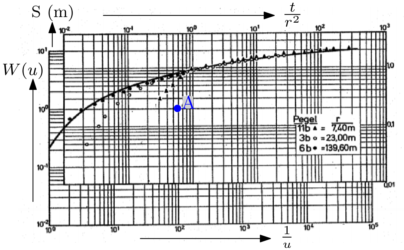
In the example:
Next, values for \(s\) and \(t/r^2\) at the match points are determined. In this example:
Next, we obtain \(T\) from \(T = \frac{Q}{4\cdot\pi\cdot s }\cdot W_A\). For \(Q = 26.7\) L/s, we obtain \(T = 1.06 \cdot 10^{-2} \) m2/s. Finally, \(S\) is obtained from \(S = \frac{4 T\cdot t/r^2}{1/u_A}\). In this example: \(S = 2.42 \cdot 10^{-4}\)
7.6.5. Computer-Based Comparison of Data and Type Curve#
The data in the type-curve can now easily be fitted using computer simulations. The Fig. 7.10 is from the Wells. The simulation tool Type curve and fitting pumping data tool provided can be used to fit user data to the type curve.
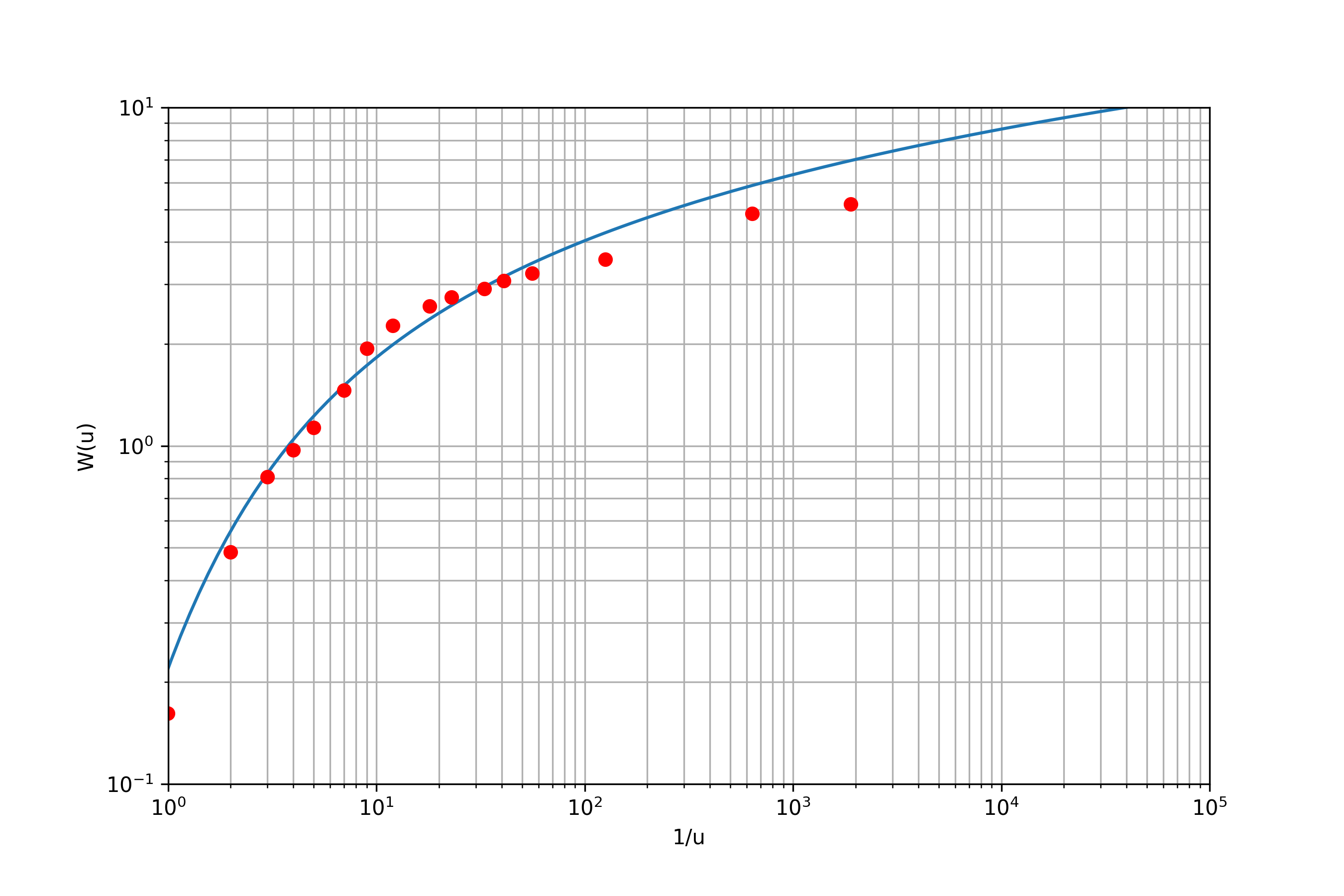
Fig. 7.10 Computationally fitted data to the Type curve#


